The Devlin Q-Series key caps from UKKeycaps arrived, and I now have a keyboard that looks like a keyboard.
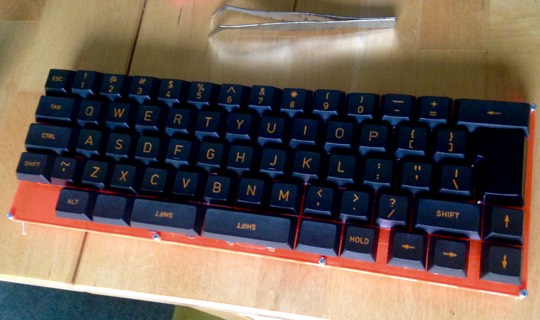
I can type on it and nothing happens because, alas! Keyboard X-1 has no brain.
There are three main next steps:
- Write the firmware for its micro-controller brain.
- Wire the controller board in to the column and row rails.
- Design and cut the remaining pieces for the case.
Keybrain firmware
The Teensy LC comes with instructions for modifying the Arduino IDE to work with this board. Using the IDE to write a program to blink the LED on the board at different rates is easy enough but the keyboard controller is going to involve enough complexity that I would like to be able to use my familiar programming tools—unit testing, Sublime Edit, Makefiles, and so on. The Arduino site is annoyingly coy about the fact that it is in fact programmed in standard C++ using the GNU tool-chain. Which should mean I can write my code with all the facilities of C++11.
After a bit of experimentation I have come up with what I hope will be a productive approach involving writing components with unit tests in Sublime Edit using Google Test (chosen more or less at random from the alternatives). The tests—and the mock hardware API they run against—can use the full C++ library, so long as the components themselves limit their use of facilities not available in the library on the board.
I have written code to scan the matrix and make a list of closed switches. The remaining jobs are to test this on hardware (rather than just unit tests) and to convert lists of closed switches in to key combinations and assemble USB status packets va the USB keyboard library.
Wiring in the brain
The excitement here is that if I get the soldering wrong I could easily wreck a component that will cost £13.50 to replace. I have been sketching out a wiring diagram to try to get each row and column to the controller as neatly as possible.
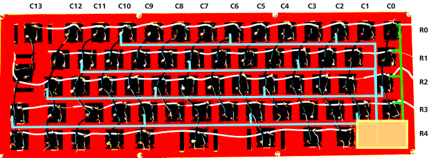
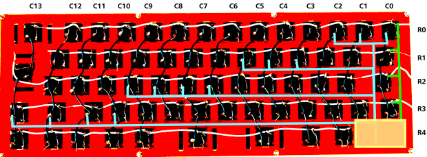
After a few iterations the second of these seems like a good approach. My aim is to squeeze the controller in to the keyless gap to the left if the space-bar row (indicated by the yellow rectangle in the above diagrams).
Next step: soldering wires to the controller, and then testing whether I have fried it in the process!