I have been making a hand-wired computer keyboard and now is as good a time as any for a status update.
Plate
Previously in this saga I had created software for drawing the plans for the top plate. In order to calibrate the process I added a way for it to generate a test piece with several switch holes, each slightly different in size. Nonsensically enough I neglected to bring a copy of the files with me to the Hackspace. Instead I had to borrow their Windows-10-powered CAD machine and install Microsoft Visual Studio Code, GitHub Desktop, and Python so I could run the program there and then.
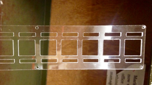
Having cut the tester, I measured it every way I could think of with a friend’s vernier calipers to calculate the kerf value for this cutter, and the desired size of the holes. I fed these tweaks back in to the script and generated drawings for the plate and under-plate proper. Some trepidation as I committed my acrylic sheets to the laser.
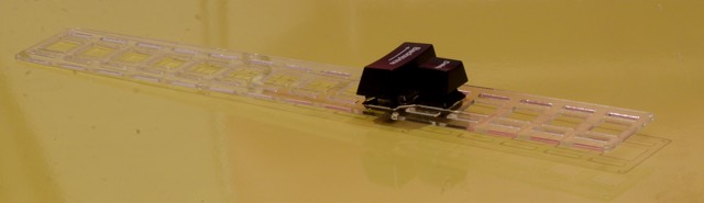
As it turns out there was one problem with the design: while I allowed 0·75 mm in the under-plate for the clips of the stabilizers, they actually needed a little more. As a result the two layers were forced a little apart by the stabilizer clips. I addressed this with a little filing. Luckily it is in a place that should not show in the finished keyboard, because the transparency of the acrylic makes the filed sections look messy.
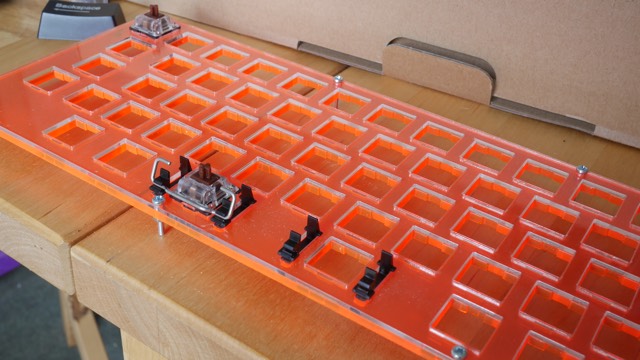
Another issue was differences in tolerances between the acrylic sheet I wanted the switches to clip in to and the tolerances of the clips themselves: the acrylic is nominally 1·5 mm but I measure it as almost 1·6 mm. Now this is in tolerance for its intended use but might be the reason why my switches do not clip in as firmly as I would have liked.
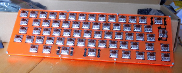
Plan is to wire it up as tightly as I can and then see whether it needs a spot of glue as well.
There are more photos in my Keyboard Plate album on Flickr.
Next
The next step is wiring up the matrix circuit.