I spent part of the Easter weekend finishing of phase I of the wiring of my keyboard: the matrix.
Rows of diodes
The next step after cutting the plate is wiring up the matrix circuit.
The first part of this is soldering a diode to one pin of each switch and soldering these in turn to horizontal output wires.
Since the wire will be preforming a second duty in holding the switches in place, I wanted single-core breadboarding wire, since that is sitiffer and easier to handle than multicore wire. For convenience I bought some from HobbyTronics in a variety of colours, along with snips and a Teensy LC board. They arrived in an adorably tidy package.
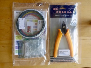
Ordering via HobbyTronics also gave me the opportunity to buy M2 screws in lots of less than 250 at a time.
After a bit of faffing about my technique for the diodes—such as it is—is as follows:
-
Tear off one row’s worth of diodes from the roll. The red strip shows which end goes down.
-
Bend them against the table edge a few mm above the diode.
-
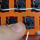
For each switch, bend the kink made in step (2) in to a loop and pull it as small as possible.
-
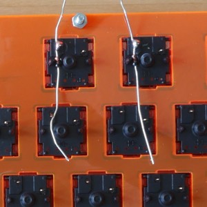
The loop goes over the left pin of a switch, so the glass bead of the diode rests between the plastic pegs of the switch. Press it down (mostly using my thumbnail as a tool here).
-
Solder the loop and pin together: press the iron against both wires for a few seconds and then melt the solder wire over them. I found if I removed the solder a moment before the iron I could see the solder flow over the two wires hopefully making a strong join.
-
Repeat for one row of switches.
I managed to get the diode fairly consistendly snuggled between the plastic pins on the underside of the switch.
Output rails
The other end of these diodes all need to be wired to the same output pin of the microcontroller. So the two options for the next step are to first solder them to each other (what you could call Brownfox style) or to a wire serving as the output rail (as described in the ‘Modern Handwiring Guide: Stronger, Cleaner, Easier’). I went for the second option.
I bought myself an automatic wire-stripper. This is a great tool for this job.
-
Estimate around 5 mm of wire per joint and strip that much insulation (say 70 mm) off the end.
-
Laying the wire out along the row guestimate the amount of insulation beteween joints and mark the spots in the insualtion with your thumbnail.
-
Use the stripper to cut the insulation at these spots. The bits of insulation should remain threadeed on the wire.
-
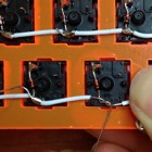
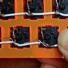
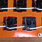
For each joint, I bent the diode wire up over the rail wire, then sort of twisted them around each other to make a loop.
-
Solder the loop.
-
Push the piece of insulation sleeve back against the new joint. Ideally it will reach just to the point where the next didode will cross the wire.
-
Repeat for all te diode-to-rail joints.
Here is a sequence of photos showing the loop process:
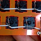
In the finished circuit, the microcontroller will ‘listen’ to a rail to see whether one of the switches on that row is pressed.
Column rails
The columns are the inputs used to connect the other pin of the switch to ground.
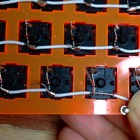
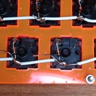
The technique for this was essentially thr same: stripping off a 25–30 mm form the end, then making gaps in the insualtion for each of the joints, looping the bare wire around the pin and soldering the loop. The loops were easier to do than fiddling with both the diode and the wire at the same time.
As I was preparing the next loop I was also pressing the wire down as firmly against the plate as I could—and at the same time pressing the switch in to place. The idea was that hte wire itself will be holding the switches in position in the plate.
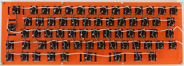
The main gotcha is that because keyswitches are staggered, the columns are actually zigzags and on two occasions I zagged when I should have zigged and soldered it to the wrong switch. This was correctiable with a bit of snipping and desoldering but obviously it would have been be neater if I had avoided doing that. See if you can spot the extra join.
Next
The next bit of work is installing its brain—both soldering in the microprocessor board and writing the firmware (or adapting one of the free-software keyboard firmwares that are available).